
Workshop - Fuel Feed
Details for this section are for the Lambretta 175 Li Series 1 and 2 however there are many similarities between these models and other models of Lambretta threewheelers/Lambros.
This information and the pictures included are provided from the 'Instructions for Repair Shops' for these models published in 1963. It is intended for informational purposes and we would recommend seeking professional advice before undertaking anything described in the Workshop section.
Fuel Tank
The fuel tank is fixed to the cabin structure by two straps lined with felt. To remove, unscrew the two trunnions on the lower part.
The tap, screwed into the lower part of the tank, is fitted with metal net filter. When substituting, vary the number of gaskets, so that when the tap is screwed in, it is in the proper position.
The filler cap has an air vent hole with tube. Should fuel starvation occur, check if vent hole is not blocked. Then check if the flow of petrol through the tap is good. When filling up, take care that no fuel whatsoever is not spilled on to the instrument panel.
| theLambro tip: fuel flow is a major fault on Lambros and Lambrettas. If you are experiencing problems which you suspect relate to fuel, before adjusting jetting you should first check fuel flow from the fuel tap. The rate of flow for a standard engine should be an absolute minimum of 170ml per minute. The optimum flow is 220 - 250mls per minute. If your flow is slower than this, we would recommend first cleaning the tap and if this does not remedy the slow flow, replacing the tap. Tuned engines will need a much higher flow. |
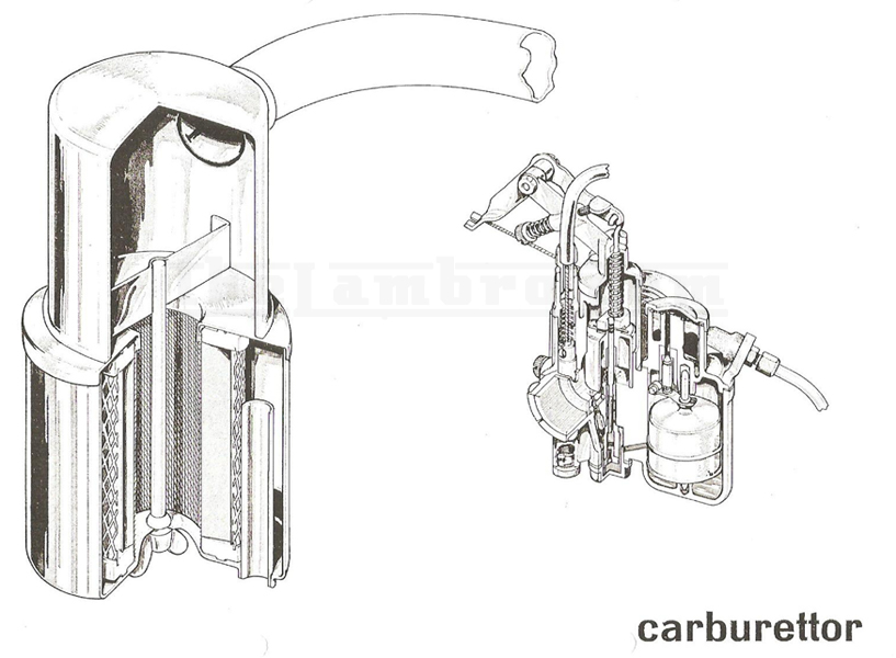
Carburettor
Please refer to specific model pages in the information section for carburettor types and jetting
The choke control is by cable, by turning the knob half a turn. This knob is situated on the dashboard to the left of the steering column.
The conical needle has three position groove and acts on the atomizer of the main jet. The usual position is on the middle grove.
Max. Jet - is situated in the jet holder and can be reached by unscrewing the banjo nut at the bottom of the mixture chamber. (14 mm ). The jet is unscrewed by screwdriver. The jet holder is situated in the lower part of the carburettor body, and can be removed by using an 8 mm box spanner.
The pilot jet is situated in a side cavity of the chamber and can be removed by proper screwdriver.
The starter jet is situated in the side of the chamber plug and can be removed by means of an 8 mm spanner.
The fuel filter is situated in the cover in correspondence to the inlet tube connector and can be reached by removing the central screw fixing the cover.
Adjustment
When reassembling the engine, ensure that the carburettor is fitted with the bowl perfectly vertical in respect to the ground, and that the connecting hose from carburettor to the inlet manifold is blocked to avoid air infiltration.
The choke control is adjusted by means of the adjuster placed at the extremity of the curved tube of the choke cable.
 It is necessary to check that the choke cable is not in tension when the choke knob is in the rest position, and allows an axial movement of the cable guide tube of 1mm. If this is not so, the slide would remain partially opened causing starting difficulties when engine is hot, (when the choke control should not be used), irregular slow running and high consumption.
To adjust the slow running, which should be done with hot engine, act on the adjuster screw on the throttle (See Fig. 26 by screwing screw No. 1 the valve opens) and on air adjuster screw (See Fig. 26 screwing screw No. 2 the air inlet is reduced enriching the mixture.
Proceed in the following manner:
1) With engine running and throttle control closed, act on screw No. 1 which regulates the closure position of the valve so as to attain a fast engine speed of 1000 to 1200 R.P.M.
2) Adjust screw No. 2 so as to attain a more regular running; fast running indicates rich mixture, unscrew No. 2 - if the engine has a tendency to stop, this indicates weak mixture and so tighten No. 2.
3) Act on screw No. 1 to eventually reduce the engine revs if necessary and adjust No. 2, Usually the air adjuster screw should be unscrewed by 1/2 to 1 1/2 turns from complete closure.
After having adjusted the slow running according to the above rules, check if by opening throttle valve slowly, the engine tends to slow down or stop. This means weak mixture, so screw down lightly the air screw until the phenomenon disappears.
With the adjustment, it is assumed that the carburation is correct at all speeds. If however for engine speeds at 1/2 to 3/4 throttle it is felt that the mixture is too rich or too weak (this can occur on carburettors in bad condition after long service), the carburation can be corrected by altering the position of the needle to the first notch (weak mixture) or the third notch (rich mixture).
Air Filter
The air drawn in by the carburettor is filtered through a filter placed on the rear right hand cabin strut. The filter consists of a box and dry cartridge. The cartridge can be reached by unscrewing the wing nut on the lower part of the filter box and removing the cap container fixed in the cabin.
The cleaning of the filter cartridge (generally every 2500 miles or more frequent according to the conditions) is done by skaking or blowing with low air pressure. Do not under any circumstances wash in petrol ,oil or water.
A dirty filter will cause a richening of the fuel mixture, causing had acceleration, low power and high consumption
The filter is connected to the carburettor by a rubber hose, which must always be kept tightly fitted to avoid air infiltration. A bleed valve is fitted to the hose which prevents any inlet of non filtered air during the running, but allows for the draining of any surplus fuel from the carburettor. The valve, consisting of a plate and a diaphragm is reached by removing the oil collecting cup and its clip. The valve can be cleaned in petrol. To check its functioning after reassembly, immerse the end of the drain tube into a cup full of petrol and at various engine speeds no petrol should be drawn up the tube, instead air bubbles should be seen in the cup itself.
Care must be taken to ensure that the drain tube is clipped to the frame or rear of the cabin, so that it does not touch the exhaust pipe and drip petrol on to it, otherwise a fire could break out.